Left is a gif of my working circuit! As you can see, each red LED blinks independently.
Left is a gif of my working circuit! As you can see, each red LED blinks independently.
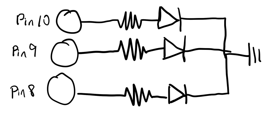
Above is the schematic that shows my usage of three pins(Pin 10, 9, and 8), three resistors (each 220 Ohms), and three LED lights that all connect back to ground.
          // the setup function runs once when you press reset or power the board

          void setup() {

            // initialize digital pin LED_BUILTIN as an output.

            pinMode(8, OUTPUT);

            pinMode(9, OUTPUT);

            pinMode(10, OUTPUT);

          }


          // the loop function runs over and over again forever

          void loop() {

            digitalWrite(8, HIGH);  // turn the LED #1 on (HIGH is the voltage level)

            delay(1000);                      // wait for a second

            digitalWrite(8, LOW);   // turn the LED #1 off by making the voltage LOW

            delay(1000);                      // wait for a second

            digitalWrite(9, HIGH);  // turn the LED #2 on (HIGH is the voltage level)

            delay(1000);                      // wait for a second

            digitalWrite(9, LOW);   // turn the LED #2 off by making the voltage LOW

            delay(1000);                      // wait for a second

            digitalWrite(10, HIGH);  // turn the LED #3 on (HIGH is the voltage level)

            delay(1000);                      // wait for a second

            digitalWrite(10, LOW);   // turn the LED #3 off by making the voltage LOW

            delay(1000);                      // wait for a second


          }
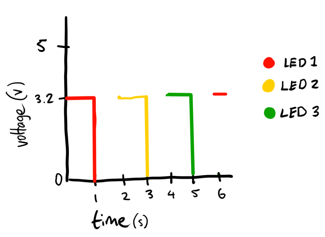
The code above allows the LEDs of different pins to blink.
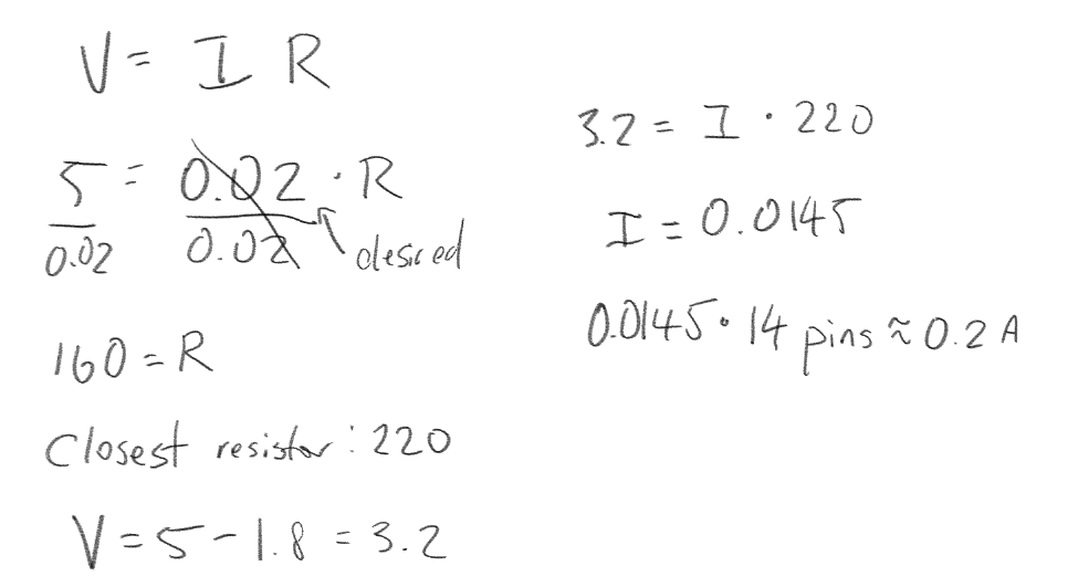
The number of LEDs that can be blinked independently would be 14, which would draw about 0.2A. This is explained below.
The speed of that the lights could be blinking independently was around 10 ms for me to be unable to keep up.