Here is all the documentation for assignment 5!
Here is all the documentation for assignment 5!
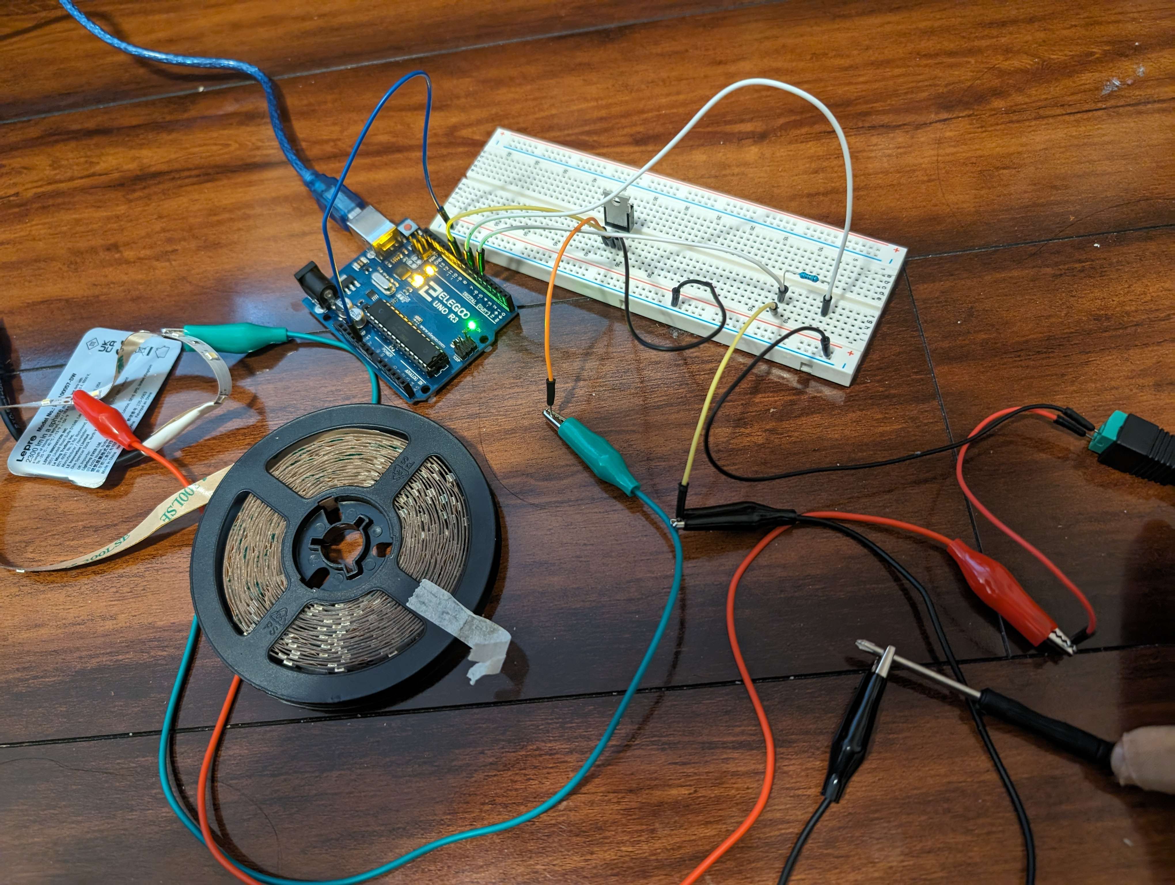
Above is my circuit, which fades on the LED strip when my mother touches the screwdriver!
The most current the transistor could handle is 80A, according to the datasheet.
#include // allows the use of the CapacitiveSensor library, which acts as the input
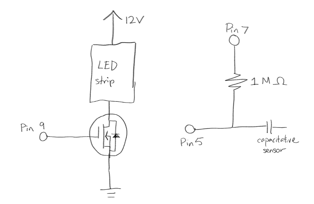
CapacitiveSensor cs_4_2 = CapacitiveSensor(7,5); // 1 megohm resistor between pins 7 & 5, pin 5 is sensor pin, add wire, metal thing
int ledPin = 9; // LED connected to digital pin 9
//runs once at setup
void setup() {
Serial.begin(9600); //beings the serial monitor
}
//runs repeatedly
void loop() {
long start = millis(); // returns the number of milliseconds since the device begins running the program
long total1 = cs_4_2.capacitiveSensor(30); // runs a sensor check 30 times to avoid errors and filters for bad data
Serial.print(millis() - start); // check on performance in milliseconds
Serial.print("\t"); // tab character for debug window spacing
Serial.println(total1); // print sensor output 1
delay(10); // arbitrary delay to limit data to serial port
if (total1 > 500) { //checks if screwdriver is being touched
// fade in from min to max in increments of 5 points:
for (int fadeValue = 0; fadeValue <= 255; fadeValue += 5) {
// sets the value (range from 0 to 255):
analogWrite(ledPin, fadeValue);
// wait for 30 milliseconds to see the dimming effect
delay(30);
}
}
}
It should be 80A. Pins 2 and 3 and the drain and source, which means that the maximum current that could be handled between them should be the maximum the entire transistor could handle.
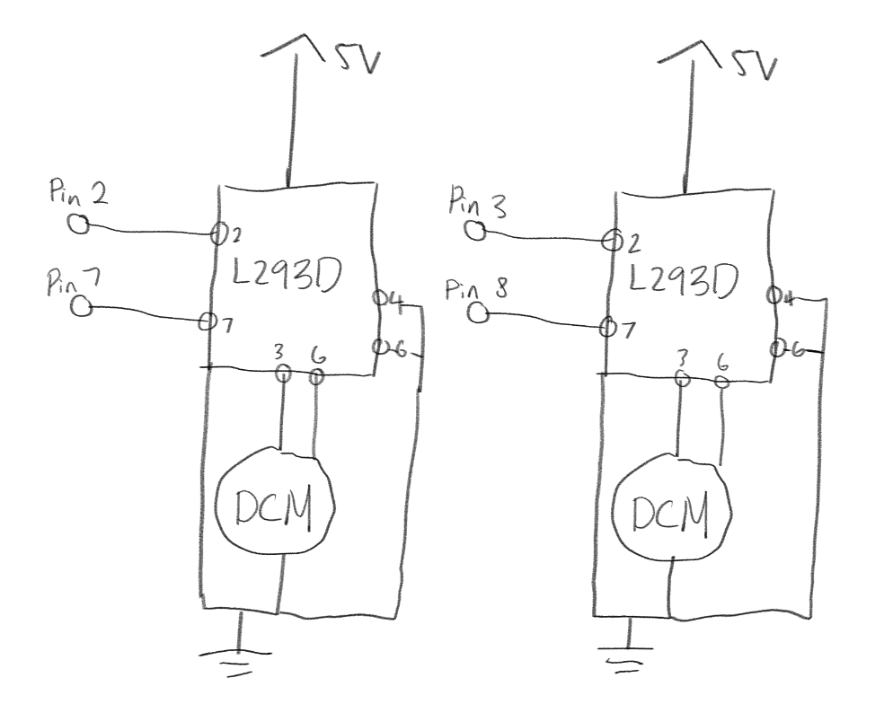
        //pin 2 and 7 are pairs in the Arduino

        //pin 3 and 8 are pairs in the Arduino

        // both pairs are connected to the L293D's pins 2 and 7 that can manipulate the direction of the motor


        // both motors FORWARD

        pin 2 HIGH

        pin 7 LOW

        pin 3 HIGH

        pin 8 LOW


        // one forward, one back

        pin 2 HIGH

        pin 7 LOW

        pin 3 LOW

        pin 8 HIGH


        // one back, one forward


        pin 2 LOW

        pin 7 HIGH

        pin 3 HIGH

        pin 8 LOW